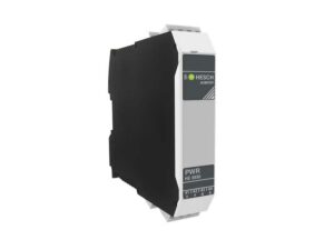
Communication with the fieldbus coupler takes place via an asynchronous serial RS-485 connection.
The outputs can be operated in a predefined clock mode to adjust the power of the actuators.
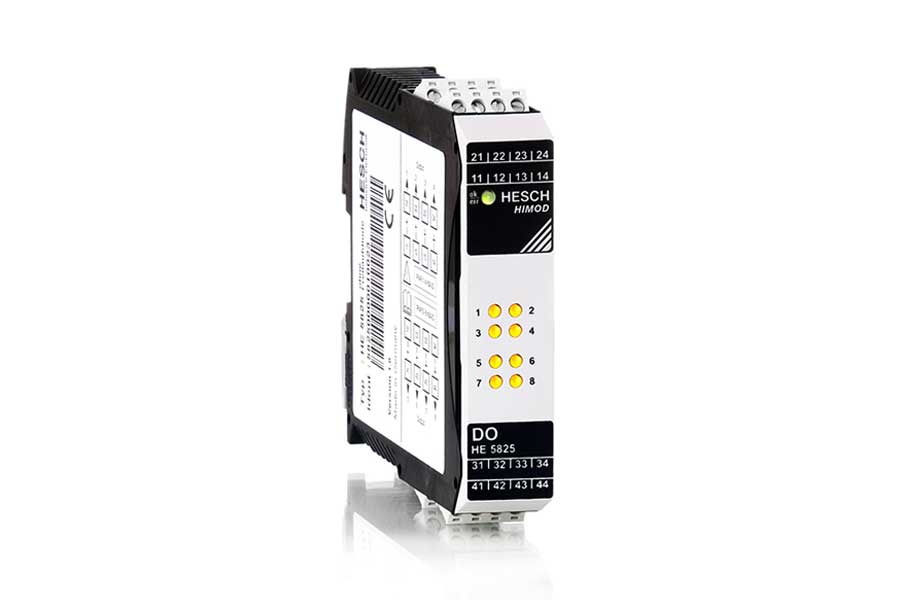
The signal state of the digital outputs is indicated via status LEDs. The areas of supply voltage, fieldbus and logic are galvanically isolated from each other. Module errors and errors in case of overload, short circuit or missing supply are detected and displayed.
In the event of a fault, the outputs change to a previously defined safe status (Fail Safe).
Technical Specifications
| HE 5825 |
| Module type | HIMOD digital output module 8 x 24 V DC |
| Power supply | Over internal T-bus: 24 V DC / 7.5 V DC |
| Current consumption | Max. 40 mA at 24 V / max. 60 mA
at 7.5 V |
| Electrical isolation | 2300 Veff[((supply, logics) / per channel] |
| Digital output |
| Principle | High side driver, invertible logics |
| Supply | External supply, 18…32 V DC |
| Load | Static with 2 A per channel.
Maximum total current: 12 A |
| Cyclic operation | Can be set with cycle time and switch-on
time of 5 ms to 30 s |
| Protective mechanisms | Protected against short-circuit, overvoltage,
overtemperature, reverse voltage |
| Fail safe | Transition of the outputs to a
safe state in the event of error |
| Diagnostic display |
| 8 x yellow LEDs | Status of the outputs |
| 1 x 2-colour LED | Module status |
| Wiring technique | Screw / plug terminals, conductor cross-section 0.2…2.5 mm²
Spring clamp / plug terminals, conductor
cross-section 0.2…2.5 mm² |
| Weight | 150 g |
Errors and changes excepted
