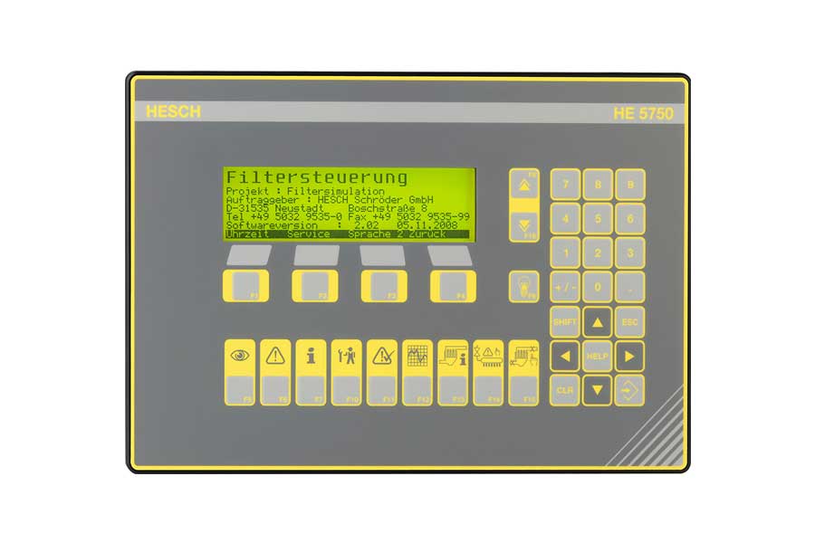


Automatic monitoring of valve and filter functions
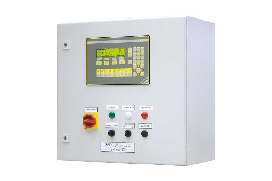
Especially large filter plants with several hundred cleaning valves and many thousands of filter bags, such as those found in waste incineration plants and cement works, should have a high degree of automated monitoring processes to ensure that the plant is always fully functional.
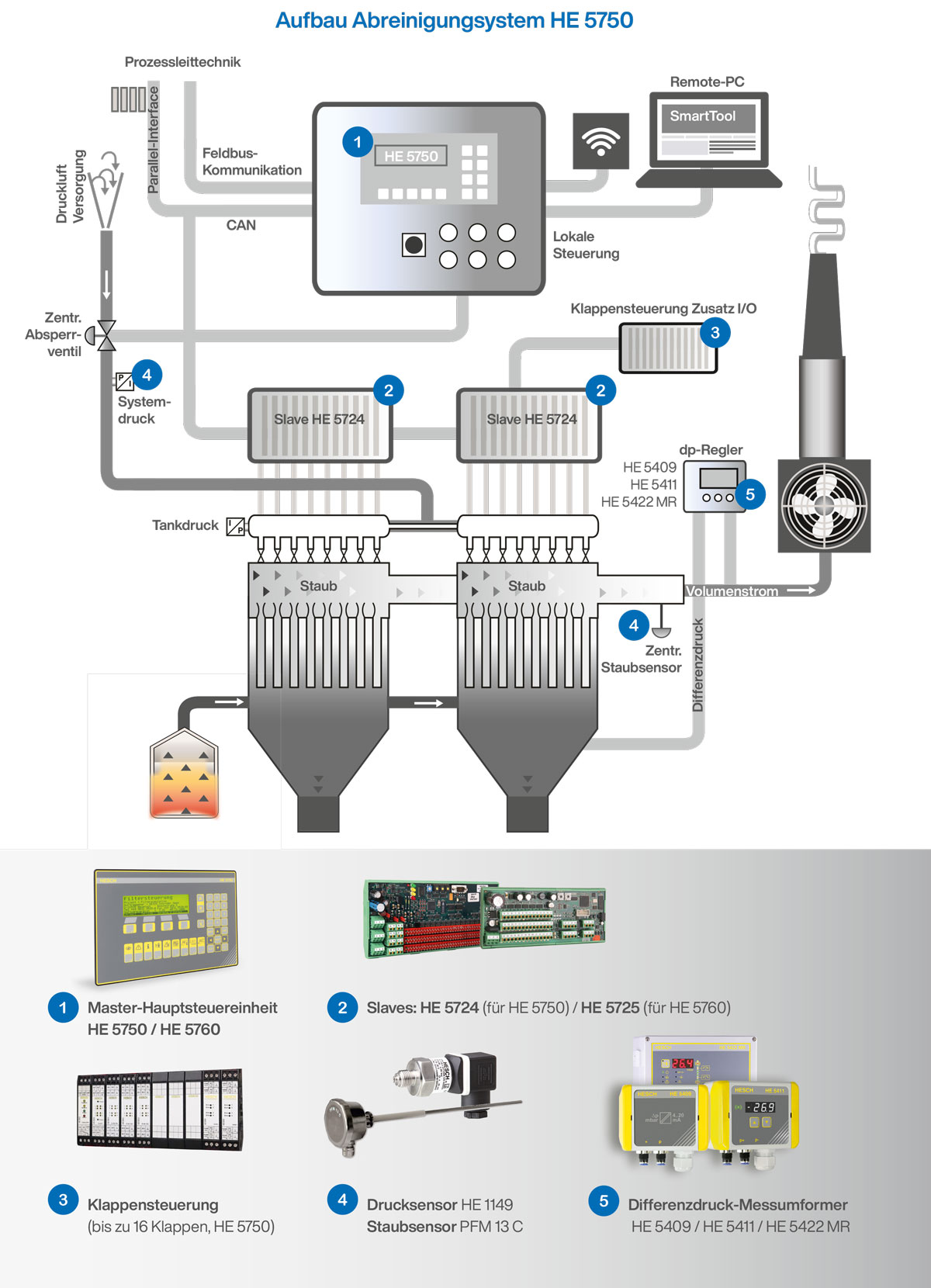
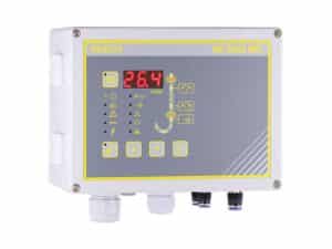
For this reason, HESCH has integrated automatic hose rupture monitoring into the HE 5750 cleaning control system in addition to extensive monitoring of the cleaning valve function. For this purpose, only one central dust sensor is optionally required, which mounted in the clean gas duct at the filter outlet, monitors the dust load of all chambers.
Old technology out – new technology in

Bring your plant up to date with the HE 5750 and sustainably reduce energy consumption.
The support program of the German Federal Office of Economics and Export Control(BAFA) and the Kreditanstalt für Wiederaufbau (KfW) provides large industrial companies with 30% funding* for energy efficiency improvements.
Example calculation:
By optimizing the control system, operators of dust collection systems can reduce power consumption by about 10 % when using a 500-kilowatt suction hoist. At a kW price of € 0.08, they save around € 35,000 in energy costs per year.
*Subject to legal changes. We do not guarantee the receipt of the grant.
Pre-pressure control: new feature enables energy costs to be reduced
Saving energy is even more important today than ever before, due to recent high electricity price increases. HESCH has developed an energy-saving function for operators of large filter systems.
The new inlet pressure control optimizes the cleaning pressure. The inlet pressure control ensures that only as much compressed air is delivered as is required for cleaning the filter. The consumption of expensive compressed air is reduced. In addition, the upstream pressure control also has a positive effect on the service life of the filter media, since the filter elements are subjected to compressed air more gently than before. This lower load increases the service life of the filter elements.
The HE 5750 reports the exact position of the defective filter bag.
Accurate hose rupture localization
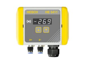
If one of three freely defined limit values of the dust load is exceeded, the control system automatically assigns this event to the respective chamber and triggers the corresponding reaction (e.g. an error message, an alarm or the shutdown of the system).
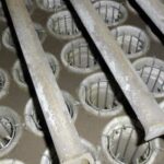
In this way, not only is fault-free operation guaranteed at all times, but in the event of a hose rupture, immediately a message is also generated with the exact position of the damaged hose row.
This considerably minimizes the time required to locate a defective filter bag and thus increases the availability and efficiency of the system.
We will be happy to advise you without obligation, please contact us.